📋 Table of Contents
- What is LOD?
- Common Confusion: LOD vs LOd vs LoD
- LOD Levels (100-500)
- Practical LOD Matrix
- Detailed Examples
- BIM Forum LOD Specification
- Practical Implementation
- Tips and Common Mistakes
📄 1. What is LOD?
LOD (Level of Development) is a measure that defines the degree of completeness and accuracy of an element in a BIM model in terms of Geometry and Non-Graphic Information.
1.1 Official Definition (BIM Forum):
"LOD describes the minimum dimensional, spatial, quantitative, qualitative, and other data included in a Model Element to support the Authorized Use associated with that LOD."
1.2 LOD Components:
- Geometry: Shape, dimensions, and location
- Information: Attached data (Material, Cost, Manufacturer...)
🔄 2. Common Confusion: LOD vs LOd vs LoD
2.1 Three Different Concepts:
| Term | Definition | What It Measures |
|---|---|---|
| LOD (Level of Development) | Development Level | Geometry + Information + Reliability |
| LOd (Level of Detail) | Detail Level | Geometry only (appearance) |
| LoD (Level of Design) | Design Level | Design phase (conceptual/detailed) |
"Level of Design" is a commonly used term in practice but it does NOT follow an official reference or standard like LOD (BIM Forum) or LOd. It is included in this comparison to help readers understand the term if encountered in projects. When using LoD in contracts, it is essential to clearly define its meaning and scope within the contract documents to avoid ambiguity.
2.2 Practical Difference:
Level of Detail (LOd):
- Focuses on geometric appearance only
- How many polygons? How much visual detail?
- Example: Low LOd column = simple rectangle, High LOd = visible rebar details
Level of Development (LOD):
- Includes geometry + information
- How reliable is this element for the intended use?
- Example: LOD 300 column = exact dimensions + concrete type + specific location
Level of Design (LoD):
- Related to traditional design phases
- AIA Design Phases: SD, DD, CD
- Example: SD = Schematic Design, DD = Design Development
2.3 Relationship Table:
| Design Phase (LoD) | Appropriate LOD | Description |
|---|---|---|
| Concept Design | LOD 100 | Initial idea |
| Schematic Design (SD) | LOD 200 | Preliminary design |
| Design Development (DD) | LOD 300 | Design development |
| Construction Documents (CD) | LOD 350 | Construction drawings |
| Construction | LOD 400 | Shop Drawings |
| As-Built | LOD 500 | Actual construction |
📊 3. LOD Levels (100-500)
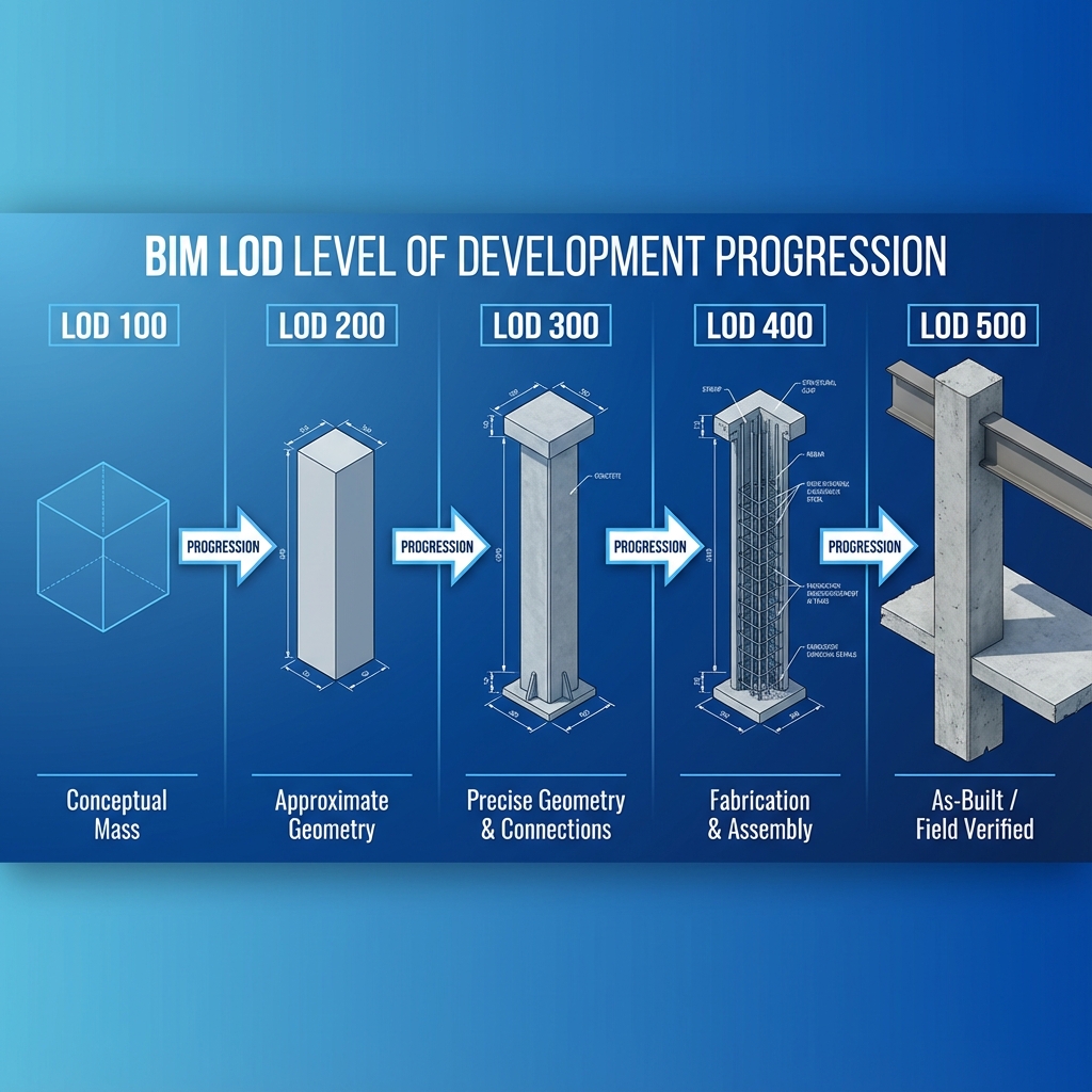
3.1 LOD 100 - Conceptual
| Item | Details |
|---|---|
| Geometry | Symbol or general shape (mass) |
| Information | Very limited (element type only) |
| Use | Feasibility studies, alternative comparison |
| Example | Cube representing entire building |
3.2 LOD 200 - Approximate Geometry
| Item | Details |
|---|---|
| Geometry | General shape with approximate dimensions |
| Information | Element type + system + approximate location |
| Use | Preliminary coordination, rough cost estimate |
| Example | Column ~40×40 in position |
3.3 LOD 300 - Precise Geometry
| Item | Details |
|---|---|
| Geometry | Exact dimensions and specific location |
| Information | Material + actual measurements |
| Use | Quantity takeoff, Clash Detection |
| Example | Column 40×40×300cm, C30 concrete |
3.4 LOD 350 - Coordination
| Item | Details |
|---|---|
| Geometry | LOD 300 + interfaces with other systems |
| Information | Coordination data with other disciplines |
| Use | Full coordination, preliminary Shop Drawings |
| Example | Column with MEP penetrations |
3.5 LOD 400 - Fabrication
| Item | Details |
|---|---|
| Geometry | Complete fabrication details |
| Information | Supplier info, installation, reinforcement |
| Use | Production, Prefabrication |
| Example | Column with full rebar and cover |
3.6 LOD 500 - As-Built
| Item | Details |
|---|---|
| Geometry | Actual constructed (documented) |
| Information | Operation and maintenance data |
| Use | Facility Management |
| Example | Column at actual location + maintenance log |
📐 4. Practical LOD Matrix
4.1 LOD Matrix Example:
| Element | SD | DD | CD | Construction | As-Built |
|---|---|---|---|---|---|
| Columns | 100 | 200 | 300 | 400 | 500 |
| Beams | 100 | 200 | 300 | 400 | 500 |
| Slabs | 100 | 200 | 300 | 350 | 500 |
| Walls | 100 | 200 | 300 | 350 | 400 |
| Windows | 100 | 200 | 300 | 400 | 500 |
| HVAC Ducts | 100 | 200 | 300 | 400 | 500 |
4.2 Design Phase Definitions (AIA):
| Abbreviation | Full Name | Description |
|---|---|---|
| SD | Schematic Design | Initial concept showing overall design intent, basic spatial relationships, and preliminary systems. Establishes project scope and feasibility. |
| DD | Design Development | Refinement of SD with more detail on materials, systems, and coordination. Includes preliminary structural and MEP layouts. |
| CD | Construction Documents | Complete drawings and specifications for construction, permitting, and bidding. All dimensions, details, and specifications finalized. |
📝 5. Detailed Examples
5.1 Example: Concrete Column
LOD 100 - Conceptual
Shape: General rectangle
Info: "Structural column"
Use: Feasibility study
LOD 200 - Approximate
Shape: ~40×40 approximate
Info: Concrete, approximate location
Use: Preliminary design
LOD 300 - Precise
Shape: 40×40×300cm exactly
Info: C30, specific location, Grid C-3
Use: Quantity takeoff, Clash Detection
LOD 350 - Coordination
Shape: 40×40×300cm exactly, with MEP penetrations and sleeves
Info: C30 concrete, Grid C-3, coordination data with MEP systems
Use: Full multi-discipline coordination, preliminary Shop Drawings
LOD 400 - Fabrication
Shape: 40×40×300cm with full reinforcement (8Φ16 main + 4Φ12 corners + Φ8@15cm stirrups), 25mm cover, MEP penetrations
Info: C30 concrete, Grid C-3, coordination data, supplier info, installation sequence, rebar schedule
Use: Shop Drawings, Fabrication, Prefabrication
LOD 500 - As-Built
Shape: Actual verified location and dimensions (as-built survey), full reinforcement, MEP penetrations as executed
Info: C30 concrete, Grid C-3, pour date: 15-Jan-2026, Mix Design: MD-2345, QC records, inspection reports
Use: Facility Management, maintenance records, handover documentation
📖 6. BIM Forum LOD Specification
6.1 What is LOD Specification?
A reference document from BIM Forum that specifies in detail what each element should contain at each LOD level. Covers hundreds of structural, architectural, and MEP elements.
6.2 Specification Link:
Available free at: bimforum.org/lod
🛠️ 7. Practical Implementation
7.1 How to Define LOD in Your Project:
- Define Use: What will you do with the model?
- Define Phase: Which design phase?
- Review LOD Spec: What's required for this use?
- Prepare Matrix: LOD Matrix for each element and phase
- Document in BEP: As part of EIR/BEP
💡 8. Tips and Common Mistakes
8.1 Common Mistakes:
- ❌ Requesting LOD 400 for preliminary design: Waste of time and money
- ❌ Confusing LOD with LOd: Geometric detail ≠ Development
- ❌ Not specifying responsible party: Who produces each LOD?
- ❌ Ignoring information: LOD includes data, not just geometry
8.2 Best Practices:
- ✅ Start with required use then define LOD
- ✅ Use Model Element Table (MET)
- ✅ Review LOD Spec for each element
- ✅ Train team on level differences
Next Article: IFC: Open Exchange Format - Complete Guide